YiFei Pei FX Artist / TD | CG Generalist


Breakdown

Reference
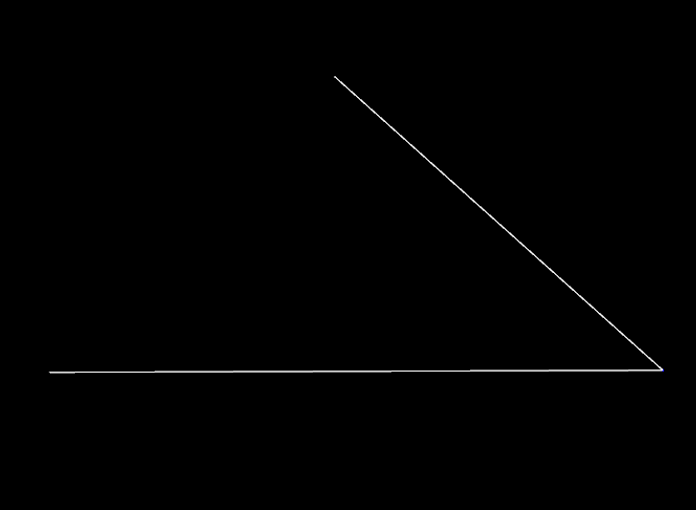
First have to simulate the animation of multiple ships floating on the ocean. Use add node to make a triangular like one in image ##. The three points in the triangle will attach to the ocean surface and follow the motion of the ocean surface, but before that, multiple ships need to be replicated. Use scatter node change the grid to points and copy the triangle to those points. The VEX can control each point to face different directions and randomly delete points to achieve irregular layout.
Attribute Wrangle node:
//randmoize rotation
float minmaxangle = chf("minmaxangle");
float angle = fit01(rand(@ptnum), -minmaxangle, minmaxangle);
@rot = quaternion(angle, {0,1,0});
//randmoize delete points
if ( rand(@ptnum) > ch('threshold') ) {
removepoint(0,@ptnum);
}

In order to match the three points in the triangle with the motion of the ocean surface, connect triangles to first input of ocean evaluate node, and the ocean spectrum that has been set up is connect to second input of ocean evaluate node. In the chop network, the lag value control how fast the ship's swing responds to the waves. If the ship wobbles badly, go to Ocean evaluate node to reduce the resolution of the ocean surface by increasing the downsample value so as to reduce the ship wobble.
In order to copy the ship model to the triangles, the VEX code will help convert the triangles to points and also retain all the previous data.
Attribute Wrangle node:
for (int i = 0; i < npoints(@OpInput2); i+=3)
{
vector p0 = point(1, "P", 0+i);
vector p1 = point(1, "P", 1+i);
vector p2 = point(1, "P", 2+i);
vector pos = (p0 + p1) / 2;
vector N = normalize(p1 - p0);
vector up = normalize(cross( p2 - pos, N));
int newpt = addpoint(geoself(), pos);
setpointattrib(geoself(), "N", newpt, N);
setpointattrib(geoself(), "up", newpt,up);
}

Then, pack boat geometry and copy the boat to points. The next step is to simulate the sails, ropes and flags. Unpack the model and use blast node to separate the pre-grouped models, and use vellum to complete the cloth simulation.
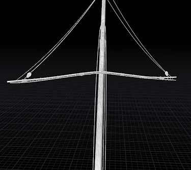
In the flags simulation, add constraints to ropes and flag. Pin the two ends of the rope to the flagpole of the ship, and glue the contact part of the flag and the rope so that it will not be separated. In the image ##, there is simulation about flag and rope.
The main sail is different from other sails. Because it is close to the camera, the difference in shape and the burning effect will enhance the impact of the picture.
The effect of the broken part of the sail cloth is completed by boolean node. Before the vellum simulation, different types of models in the sails need to be grouped according to different needs. The main sails will also be divided into three different groups: sail cloth, wood frame and flagpole.


Add constraint to sail cloth and wood frame. Increase the hardness of the wooden frame by increasing the stretch value and the bending value in the wooden frame value, because the wood frame will be slightly deformed by the force of the sail cloth and wind. Then, attach sail cloth to wood frame and flagpole and glue them together.
Sparse Pyro
Use the blast node to select the part of the sail that will simulate burning. In this time, the new spares pyro tool will be used instead of the legacy pyro. Spares workflow is same with traditional pyro workflow, only solver and smoke object are different. Convert polygons from sail to points and create density attribute. Add noise and velocity to the emission source for pyro simulation. The sail also has to be converted to a VDB volume as a static object in the simulation.

In large-scale scenes, a clear and easy-to-modify workflow is important for simulating multiple fires. Import the original boat without floating animation, and convert it to VDB, then change it back to polygon. The purpose of this step is to transform the boat which composed of different models into a complete geometry with no model blocks, that would facilitate the selection of the emission source.
The different location of fire on each boat shows that the location of the emission source on each ship is different. Remove the bottom of the boat with clip node, because only the upper part of the boat needs to simulate fire. Use Edgefracture node to break the boat to several different pieces, because the boat model itself has too many complex details, countless tiny pieces are also produced after the breaking the boat, it is very inconvenient to select the emission source and it limits the range of options. the second way is to Create a geometry similar to a stone, use a Boolean node to select the part of the boat in contact with the stone. This way looks very simple but more flexible.
Use the second way to select 5 different emission sources through Boolean node. In order to increase the details of the flame simulated by the emission source, use VOP to add noise on the emission surface and delete some parts through color attribute and repeat it again.


After adding noise to the 5 different emission sources, pack them and use the copy point node to copy them to the layout that has been set up before. delete some points that do not appear in the camera, which will save computer RAM to prevent Houdini from crash.
VEX in attribute wrangle node:
if(@uv.x < -.1 || @uv.x > 1.1) removepoint(0, @ptnum);
if(@uv.y < -.1 || @uv.y > 1.1) removepoint(0, @ptnum);
if(@uv.z < 0.1) removepoint(0, @ptnum);
There are many emission sources, but it is impossible to simulate all emission sources through one pyro solver. So grouping them and doing fire simulations separately was the only option.
In the pyro simulation test results, it is better just keep two emission sources in one area can maximize the quality of the fire and the simulation time will not be too
After copy the emission sources to the points and unpack them. Start set up sparse simulation workflow and simulate emission sources in different area sequentially. The farther away from the camera, the lower the fire quality needs to be, which can save disk space and computer RAM. Since the flame will produce a large amount of dense smoke, it is necessary to establish two different DOP networks. One is responsible for simulating the flame, the other is responsible for simulating the smoke, but make sure that the direction of the wind in the two simulations is the same.